
When photographing someone moving indoors, you use a faster shutter speed and raise ISO. The photo stays bright, but its shadows look grainy. A night scene shot on a tripod, meanwhile, can look clean at low ISO.Blaming that difference simply on high ISO misses the real cause.
This article is for photographers who already use shutter speed, aperture and ISO. It explains the sensor behavior behind those settings; no circuit knowledge is needed. Let’s start with the photos, then look inside the camera.
Keep two things separate: how much light you capture, and how brightly you render the resulting signal.
- Why does a high-ISO photo look grainier at the same brightness?
- Why does less light mean more grain?
- What changes inside the sensor when you change ISO?
- Is shooting at low ISO and brightening RAW later the same?
- When lifting shadows at high ISO, check highlights too
- How should you choose ISO when shooting?
- Common questions about ISO and noise
- Takeaway: separate image brightness from captured light
Why does a high-ISO photo look grainier at the same brightness?
Imagine photographing the same window at night with the same aperture and lighting. Make the shutter speed two stops faster and raise ISO two stops: the output brightness will be roughly the same.
f/2.8 · 1/125 s · ISO 800
Light received: 1× baseline
Lower relative graininess
f/2.8 · 1/500 s · ISO 3200
Light received: ¼ baseline
Same brightness, more visible grain
Brightening the photo with ISO cannot replace the light missed during the shorter exposure.
Keep shutter speed, aperture and lighting fixed.
1/125 s · f/2.8 · ISO 800
Captured light stays the same
1/125 s · f/2.8 · ISO 3200
Captured light stays the same
What changes is signal handling and output brightness. Compare at the same final brightness, and the proportion of light-derived noise stays the same. On a real camera, read noise and saturation matter too.
Changing from 1/125 s to 1/500 s gives the sensor one-quarter as much light at the same aperture and lighting. Raising ISO from 800 to 3200 can brighten the output, but it cannot restore the missing light.
So don’t take away the rule that higher ISO always means more noise.Changing only ISO and reducing exposure while changing ISO are different comparisons. Autoexposure and Auto ISO can make both changes happen together.
Why does less light mean more grain?
Pixels use electrons produced by light as their signal. But the electron count is never exactly identical from one exposure to the next. Even a uniform wall varies slightly in brightness, which can look like grain. This unavoidable variation in light is called photon shot noise.
Even when you photograph a uniform wall, pixels do not receive exactly equal amounts of light. Slight differences in the number of photoelectrons appear as brightness grain.
A 10-electron fluctuation is 10% of the signal.
Even a 20-electron fluctuation is only 5% of the signal.
Capture more light and the absolute variation grows, but it becomes smaller relative to the signal.
The numbers behind shot noise and SNR
In an ideal Poisson model, if the mean electron count is N, the standard deviation of photon shot noise is √N: 10 electrons for 100, and 20 for 400.
Signal-to-noise ratio is called SNR. With shot noise alone, SNR = N/√N = √N. Capturing four times the light doubles SNR from 10 to 20.
The three pixels in the diagram illustrate mean ±1σ; they are neither measurements nor random samples. Read noise, dark current and fixed-pattern effects are excluded from this comparison.
In practice, capture more light where you can. Open the aperture, lengthen the exposure, or change the lighting or camera position. But lengthening the exposure until a moving person blurs defeats the purpose.
So far, the diagrams have isolated noise caused by light. Real images also contain noise from the readout circuitry described below, and long exposures add dark-current effects.
What changes inside the sensor when you change ISO?
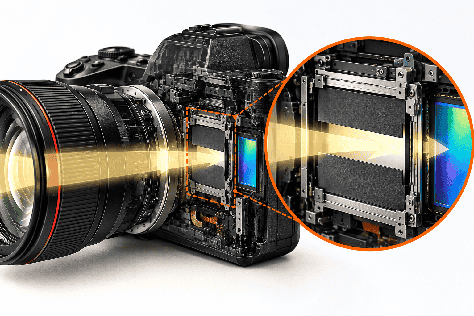
A sensor converts light from the lens into electrical signals that can be recorded as an image. Light produces electrons in tiny pixels; their quantity is read as a voltage and ultimately converted into numbers.
A sensor is an array of small pixels that convert light into electrical signals. They collect electrons produced by light, then read their quantity as a voltage.
Yellow represents light and blue the sensor. Structure and scale are schematic.
A minus sign inside a circle marks an electron. Clear the checkbox to return to the pre-transfer view. Electron counts are illustrative, not actual counts.
On some cameras, the ISO setting changes this amplification, among other things. The diagram assumes the same 100 electrons and a 1 mV → 4 mV signal.
This voltage-to-number conversion is called ADC. The 3-bit diagram is for explanation, not a camera specification. RAW recording and processing vary by camera.
ISO settings change how the captured signal is read and mapped to output, not how much light was captured.
Circuit terms and omissions
In ②, the light-receiving area is the photodiode (PD), the readout node is FD/SN, and the control between them is the transfer gate (TG). The schematic uses a representative 4T CMOS pixel and omits reset, source follower and row selection.
Electron transfer lowers the FD’s absolute voltage. Correlated double sampling (CDS) usually measures the difference between voltages after reset and after transfer. In ③, that difference is shown as a positive magnitude; the FD voltage is not shown rising. The order of CDS and ADC depends on the design.
ISO control can involve conversion gain, analog gain, digital gain after ADC, and RAW metadata. The same amplification stage does not operate in every camera, and an ISO number is not the gain factor of one circuit.
Raising ISO does not multiply the electrons produced by the same amount of light.Amplification, readout settings and the mapping to output brightness can change. Implementation varies by camera, so ISO 3200 does not imply that any one particular circuit must be active.
For a deeper look at pixels and circuitry, see How Noise Arises in CMOS Image Sensors. Here, we’ll focus on what matters for shooting decisions.
Is shooting at low ISO and brightening RAW later the same?
You might ask: if the light captured is the same, why not shoot a dark image at low ISO and lift it later? The answer depends on the camera and ISO range.
As the camera converts light into an electrical signal and reads it out, the circuitry adds small fluctuations. This is read noise. If the signal can be amplified before some of that noise is added, the same light may produce a cleaner shadow recording.
Compare RAW captures made with the same light at the same final brightness. Differences can arise because the readout circuit also adds small fluctuations. The traces isolate noise added after amplification in a schematic example.
Brightening after recording also enlarges noise added during readout.
The signal is larger relative to noise added later, so after matching brightness that noise may have less effect.
For some cameras and ISO ranges, higher ISO can produce cleaner shadow readout with the same captured light. It cannot remove grain caused by too little light.
Numerical example: noise before and after gain
The traces show only noise added after gain in a schematic example. They exclude photon shot noise and pre-gain noise. The plotted points are neither measurements nor rigorous statistical samples.
In a simplified model that includes those sources, assume a mean signal of 100 electrons, 2 electrons of pre-gain noise, and post-gain noise equivalent to 8 input electrons at gain 1. At gain 1, total variance is 168 electrons² and SNR ≈ 7.7; at gain 4, variance is 108 electrons² and SNR ≈ 9.6.
SNR = N/√[N + r_pre² + (r_post/g)²]. Assuming independent noise sources, we add variances, not standard deviations. If post-gain noise is negligible, both cases have variance 104 electrons² and SNR ≈ 9.8, so the difference shrinks.
These are not measurements of a real camera. The model omits conversion-gain switching, amplifier noise, dark current, quantization and saturation, among other factors.
Conversely, on some cameras and within some ISO ranges, RAW files made at the same exposure show little difference in shadow noise after matching final brightness. This is called ISO invariance. It does not mean every ISO has identical image quality or that capturing too little light is harmless.
A dark low-ISO RAW file also makes exposure harder to judge in the field. JPEG tone and noise-reduction processing can change, so a RAW comparison does not automatically apply to JPEG.
When lifting shadows at high ISO, check highlights too
Making the signal larger cannot extend bright-end recording without limit. Both the number of electrons a sensor can store and the capacity of its readout and digitization have limits. Once a limit is reached, distinctions between brightness levels are lost.
Higher ISO can reduce highlight headroom, but shadow read noise also changes. You cannot assume that every one-stop ISO increase always costs exactly one stop of dynamic range. Some cameras change behavior at a gain switch.
Look at both shadow grain and the highlights you want to keep. JPEG histograms and clipping warnings do not always match RAW saturation. For more, see How HDR Relates to Dynamic Range.
Technical note: high ISO and highlight headroom
A pixel running out of room for electrons is different from the circuitry or ADC after amplification reaching its output limit first. Here is a simplified model with a fixed output ceiling of 1.
At 4× gain, input ¼ reaches the same output ceiling. These are not measured ISO curves. Conversion gain, RAW recording and digital processing can change the behavior. JPEG clipping indications and RAW saturation do not necessarily agree.
Technical note: what does dual gain change?
Some sensors switch their conversion gain: the rate at which electrons become voltage. The following is one example that changes capacitance at the readout node.
In an ideal capacitor model, |ΔV| = Nq/C. For 100 electrons and capacitances of 10 fF and 2.5 fF, the voltage changes are 1.60 mV and 6.41 mV. Neither the number of electrons nor the incoming light increases. These are assumed values, not camera measurements.
The capacitance shown belongs to readout node FD/SN, not the photodiode’s storage capacity. The bottom of the circuit is a reference point in a small-signal model. Parasitic capacitance and source-follower gain also affect real conversion gain.
Dual Conversion Gain, Dual Native ISO and Canon Dual Gain Output (DGO) are not the same method. Switching points and behavior vary by camera, stills versus video, and Log settings.
How should you choose ISO when shooting?
Rather than aiming for low ISO itself, keep the shutter speed and aperture you need, and capture as much light as practical. Then use the ISO setting the shot requires.
When in doubt, this order helps you separate captured light from signal handling.
Set shutter speed for subject and camera movement. Don’t sacrifice a needed speed just to lower ISO.
Choose an f-number for blur, depth of field and lens rendering. A wider aperture can collect more light if it suits the shot.
Change lighting or camera position. For a still subject, use a tripod to lengthen exposure. If that is impractical, move on.
Auto ISO can help. Set the output brightness you want and check your camera’s normal ISO range.
If blurry, revisit ①; if light-starved, revisit ③; if highlights clip, reconsider exposure and ISO. Don’t decide by one number alone.
In aperture- or shutter-priority mode, start with the setting you care about most. Flash, video shutter angle, and Log or EI settings bring additional constraints.
| Shooting situation | What to prioritize |
|---|---|
| Moving people or sports | Secure the shutter speed you need first. A sharp high-ISO photo is often better than a blurred low-ISO one. |
| Still night scene or product | A tripod or extra lighting may let you use a normal low ISO. For long exposures, watch for dark current and subject movement. |
| High-contrast scene | Check highlights as well as shadows before raising ISO. RAW saturation and JPEG clipping indications may differ. |
For example, if you need 1/500 s to freeze a child indoors, keep that speed. If opening the aperture still leaves too little light, raise ISO. Blur and noise are different problems; lowering ISO is not always the answer.
Image stabilization reduces camera movement; it cannot freeze a moving subject. For more on shutter types, see Electronic, Mechanical and Electronic Front-Curtain Shutters Explained.
Common questions about ISO and noise
Does raising ISO always increase noise?
No. Distinguish reducing exposure while raising ISO from changing ISO alone. In RAW comparisons at the same exposure and final brightness, the higher-ISO image can sometimes have less read noise.
Does the lowest ISO always give the best image quality?
The lowest displayed ISO may be an extended setting, and normal base sensitivity depends on camera and mode. Blur and underexposure can also harm a photo more than the ISO number itself. Judge by the normal ISO range and shooting conditions.
Are larger pixels or sensors better at high ISO?
At the same illumination, exposure time and efficiency of converting light into electrons, a larger pixel can generally collect more light per pixel. Whole-image comparisons also depend on sensor area, pixel count, settings for the same framing, display size, downsampling and readout performance. Size alone cannot rank cameras.
Does switching to Dual Native ISO always make the image cleaner?
It depends on camera, shooting mode and Log settings. Shadow readout performance may change at the same exposure, but photon shot noise does not disappear. Check the official manual for that mode’s base sensitivity and limits.
How can I test my camera’s ISO invariance?
Photograph a still subject on a tripod in RAW with lighting, shutter speed and aperture fixed. Change only ISO, match brightness in processing, and compare shadows. Keep white balance, noise reduction, sharpening and display size consistent; exclude saturated areas.
Takeaway: separate image brightness from captured light
Raising ISO can brighten a photo, but it does not increase the light reaching the sensor. With less light, fluctuations make up a larger share of the signal. Depending on readout, however, a higher ISO may record cleaner shadows.
When shooting: prevent blur → choose the aperture you need → gather light → adjust ISO → check clipping and noise.This sequence gives you more useful choices than simply avoiding high ISO.
Disclaimer: This article is a general explanation to help photographers understand the principles. ISO control, RAW recording, base sensitivity and gain switching depend on the camera, firmware and shooting mode. For specific settings, follow your camera’s official manual.
Comments